
Automobile wheels are important safety components in automobiles, which have an important impact on the comfort, stability, and safety of the automobile during driving. In order to improve the strength of aluminum alloy wheels for special purposes, more and more companies are conducting analysis and research on the fatigue failure of wheels. This article takes aluminum alloy wheel hub as an example. Based on finite element analysis, bending fatigue test is carried out on automobile wheel hub to find out the structural defects and failure location of the wheel hub.
1 Finite element analysis The basic process of finite element analysis mainly has three stages. Pre-processing stage: convert the actual physical model into an ideal finite element model, and use discrete elements to replace the overall calculation domain; analysis and calculation stage: select a suitable solver according to the specific problem, and then perform numerical calculations; post-processing stage: numerical solution The results are summarized and analyzed. In finite element analysis, a clear and reasonable boundary condition is the first condition for success, and the constraints should meet the actual situation as much as possible. The boundary conditions of the numerical analysis modeling objects in this paper are clear, and the boundary conditions of the geometric model can be used to determine the mechanical boundary conditions. In the dynamic bending fatigue test of the wheel hub bending test finite element analysis model, the rim of the automobile wheel hub is fixed on the rotating turntable of the testing machine by a clamp, and the hub center uses several fastening screws to closely connect the wheel hub and the load arm. The test is based on the principle of relative motion, and the bending fatigue test analysis of the static wheel bearing aluminum alloy wheel hub Guo Weicheng
Subject to a rotating bending moment load. The bending fatigue test is used to inspect steam
Location B. From Figure 2 the bending stress distribution cloud diagram of the wheel hub in the Y direction can be
The influence of the bending load on the wheel hub during driving.
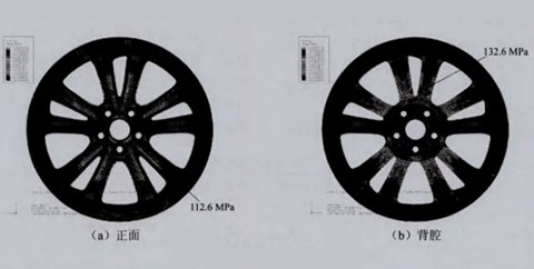
It is concluded that the maximum frontal stress appears around the center hole of the wheel training center.
The wheel hub has to withstand dynamic bending moments in the actual test.
The position near the bolt hole: the maximum stress in the back cavity appears in the
There will be different load directions, the maximum stress generated
The position near the bolt hole, up to 132.6MPa, is the most dangerous on the hub
The placement is also different.
Load the hub multiple times according to the structural characteristics of the hub
s position. Under the continuous high stress state, the damage caused by the wheel hub
Perform static analysis to determine the maximum stress distribution under cyclic loading
The damage should first appear from the back cavity and then extend to the front position.
132.6MPa
112.6MPa
L civilian car
(a) Front
(b) Back cavity
Figure 2 Cloud diagram of bending stress distribution in Y direction
Figure 3 is the bending stress of the wheel teaching in the X direction under bending load
The position of the hole is 117.5MPa; the maximum stress of the back cavity appears at
Force distribution. From the results of the stress distribution, it can be drawn: wheel hub
The spokes are close to the bolt holes, which is 105.9MPao
The maximum frontal stress occurs near the bolt around the center hole of the hub
117.5MPa
105.9MPa
2
(a) Front
(b) Back cavity
Figure 3 Cloud diagram of bending stress distribution in X direction
2 Hub bench test analysis
30% of the melting point of the material.
Before the test, the wheel should be closely matched with the connecting parts on the testing machine
2.1 Determination of test bending moment
Use bolts and nuts for standard wheel installation, and apply
The test bending moment is determined by equation (1):
Tighten the torque at 115% of the specified torque and fix the hub in the test
M=(uXR+d)XFXS
(1)
The supporting surface of the machine. During the test, always monitor the nut
Where: M is the bending moment, Nom; μ is the friction between the tire and the road
Torque, and make the loading system maintain the rated load, apply the load
The coefficient is set to 0.7: R is the static load radius, which is determined by the wheel factory or
The error does not exceed ±2.5%. If the bolt breaks during the test
The maximum static load of the tire specified by the automobile manufacturer
If the bolt is cracked, the test is allowed to continue after replacing the bolt. Sample under high speed rotation
Radius, m; d is the offset distance of the wheel (the inner offset is positive, the outer offset is
The occurrence of self-heating may affect the fatigue life and strength test results.
Negative), according to the regulations of the wheel factory, m; F is the maximum rated load of the wheel,
Make an impact. If this happens, it is recommended to reduce the test frequency
Specified by the wheel factory or automobile manufacturer, N:S is the strengthening test coefficient
rate. For the test at room temperature, the temperature of the sample should not exceed the test material.
2.2 Test failure judgment criteria If any of the following phenomena occurs during the test, the test is considered to be invalid:
① There are visible cracks in any part of the wheel hub;
②One or more nuts are loose and the torque drops, which is lower than 60% of the initial torque;
③The wheel hub cannot continue to bear the load to the required number of cycles. Test conditions: bending moment load of 3235N・m, initial torque of nut 105~l15N, required number of revolutions of 200,000~1.8 million r.
2.3 Analysis of test results After the hub reaches the required number of cycles under the specified bending moment load, it is removed from the bending fatigue testing machine, and the various surfaces and sections of the hub are inspected by color penetrating or fluorescent flaw detection. If there are no cracks on each detection surface, the wheel is deemed to have passed the bending fatigue test; on the contrary, it is deemed to have not passed the test. If the offset of the loading point exceeds 20% of the initial full-load offset before the number of cycles required by the test is reached, the wheel test shall be deemed to have failed.
The results of the bending fatigue test of the wheel hub samples are shown in Table 2. Table 2 Wheel hub bending fatigue test results. It can be seen from the test results that when the bending moment load applied during the test is 3235N・m and the test machine revolution is up to 5.85 million r, cracks will appear at the junction of the hub back cavity center and the spokes. , And the front side still has no cracks; under the condition of the same load, when the number of revolutions is increased to 7.72 million r, cracks appear in the back cavity of the hub first, then extend to the side, and then reach the front of the spokes, and finally cause the spokes to produce penetrating fractures .
Conclusion: 1. The bending stress analysis results of the finite element method for aluminum alloy wheels show that the stress in the bolt holes near the wheel center and the spokes is relatively large, which is easy to damage. There is also a certain high stress area at the junction of the spokes and the rim. In a dangerous position.
2. The aluminum alloy wheel hub has undergone a bench test, and its bending fatigue failure position is basically the same as the simulation result. Therefore, the finite element calculation method can be used to find the most dangerous position in the wheel structure, and then improve it.
About Our Services
As a professional China's leading alloy wheel manufacturer, Jihoo Wheels offers:
- 2,000+ wheel models across all major sizes and styles
- 50,000+ wheels in stock for fast, ready-to-ship orders
- Custom wheel design ― send us your style references, and our designers will create a wheel that matches your vision
- OEM and ODM production tailored to your specifications
Can't find the style you need? Email us at jihoowheels@jihoosh.com with your requirements, and we'll source or design the perfect wheel for you.
Discover quality wheels and exceptional service with Jihoo Wheels ― your reliable China wheel manufacturer.

